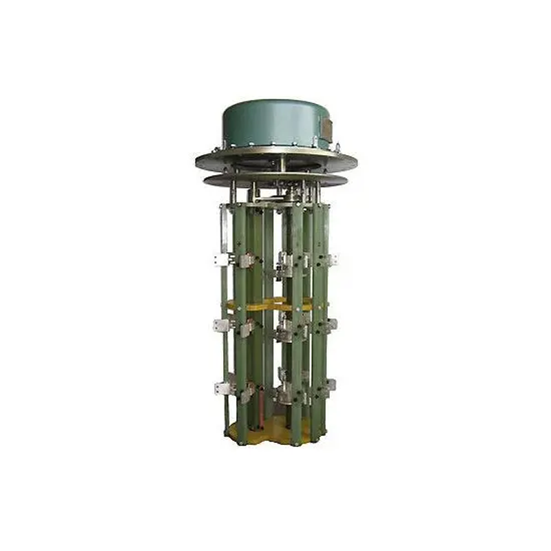
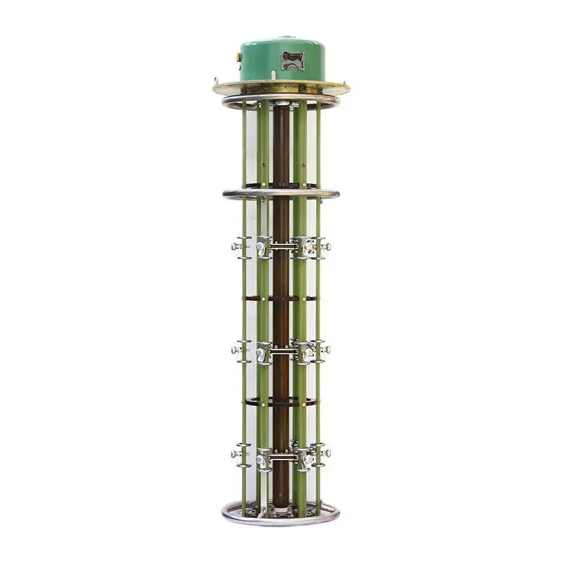

WSLD Series electric cage tap changer
discuss personally
Model
WSⅢDL800/35-5x5-10x10
WSⅢDL630/35-5x5-10x10
WSⅢDL400/35-5x5-10x10
WSⅢDL200/35-5x5-10x10
WSⅡDL800/35-6x5-10x9
WSⅡDL630/35-6x5-10x9
WSⅡDL40035-6x5-10x9
WSⅡDL200/35-6x5-10x9
WSLⅢDL800/10-5x5-10x10
WSLⅢDL630/10-5x5-10x10
WSLⅢDL400/10-5x5-10x10
WSLⅢDL200/10-5x5-10x10
WSLⅡDL800/10-6x5-10x9
WSLⅡDL400/10-6x5-10x9
WSLⅡDL630/10-6x5-10x9
WSLⅡDL200/10-6x5-10x9